
Welding copper and its alloys: technologies, modes and secrets of a quality weld
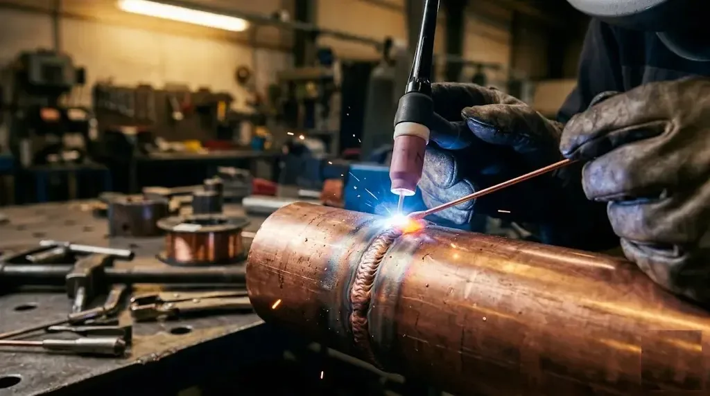
Welding copper and its alloys requires a special approach because of the metal's high thermal conductivity (390 W/m·K) and its tendency to hydrogen embrittlement. The main methods are argon-arc (TIG), gas and manual arc welding. The key conditions for success: preheating to 300–500°C, the right choice of filler and shielding gas.
Why copper is difficult to weld — physical properties and their effect
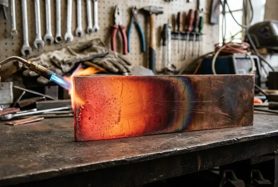
Let us explain why copper is considered one of the hardest metals to weld — four key physical properties that determine the technology.
High thermal conductivity of copper — the main reason for preheating
Its thermal conductivity is about 390 W/m·K — that is 5–6 times higher than steel and 10 times higher than stainless steel. Heat from the arc instantly dissipates into the mass of the part, so the weld pool does not form without preheating: thick-walled copper busbars or pipes require heating to 500–600°C, thin sheets — 300–400°C. In practice this means that welding cold copper with the same settings as steel is pointless — the arc burns but the metal remains solid. In local workshops in winter, when the part is additionally cooled by cold air, the weld simply will not fuse without a gas torch or inductor. Because of this property, experienced welders always check the heating temperature with a pyrometer — it is almost impossible to determine 350°C or 500°C by eye, and underheating causes lack of root penetration.
Hydrogen embrittlement — the cause of weld porosity
Hydrogen embrittlement (“hydrogen disease”) occurs when hydrogen dissolved in molten metal is released as bubbles during cooling and forms pores in the weld. The main source of hydrogen is moisture on the surface of the part — oil residues, condensation, even fingerprints, which break down into hydrogen and oxygen when heated. The solubility of hydrogen in liquid metal drops sharply during solidification, and the gas does not have time to escape from the pool, remaining as pores from 0,1 to 1 mm in diameter. This problem is especially critical on the thin-walled tubes of air conditioners or radiators — pores make the weld leaky under pressure. Before starting the process, always clean the edges to a metallic shine with a stainless steel brush and wipe with acetone — this is the only way to reliably avoid porosity.
Oxidation of metal during heating and its consequences
When heated, an oxide Cu₂O forms on the metal surface; it has a melting point higher than that of pure copper and does not dissolve in the melt, creating brittle inclusions in the weld. These inclusions act as stress concentrators — the weld loses strength and ductility, especially under vibration loads on copper busbars in electrical panels. The oxide film is removed by mechanical cleaning to a shine, and in gas welding — with fluxes based on borax (for example, a mixture of borax and boric acid). In argon-arc welding, filler rods with deoxidising agents are used — phosphorus (grades CuSn6P, CuSi3Mn1) or silicon, which bind the oxygen in the melt. If you are welding brass or bronze, choose the filler strictly for the alloy: brass needs rods with silicon, which suppress zinc evaporation, while tin bronze needs ones with phosphorus for deoxidation.
High coefficient of thermal expansion — risk of cracking
The coefficient of thermal expansion (CTE) of copper is about 1,5 times higher than that of steel, which creates significant shrinkage stresses during cooling and can lead to hot cracks. This is especially noticeable when welding massive parts — copper anodes, thick-walled pipes from 50 mm in diameter, where shrinkage reaches 2% of the weld length. If you weld with a continuous bead from start to finish, the metal at the end of the joint experiences tension, and a crack runs along the weld axis or along the fusion boundary. To compensate for shrinkage, on thin-walled parts (up to 3 mm) backing is used — a graphite or copper plate is placed on the reverse side to hold the molten pool and let it crystallise without flowing out. On thick walls the weld is made with interruptions — weld 30–40 mm, let it cool to 200–300°C, then the next section, which reduces peak stresses and prevents cracking.
Argon (TIG) copper welding — technology, gases and modes
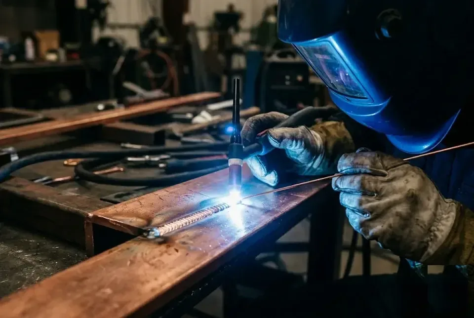
Tungsten inert gas (TIG) welding — the main method for copper and its alloys. Let us look at which gases, fillers and parameters ensure a quality weld.
Which gas to choose — argon, helium or their mixture
In TIG welding of copper, pure argon (up to 3–4 mm) is used, an argon+helium mix (5–10 mm) or pure helium (over 10 mm). Pure argon gives a stable arc and a flow rate of 8–12 l/min at a current of up to 200 A, but from a thickness of 6 mm it starts to fall short: because of copper's thermal conductivity the pool becomes narrow and penetrates the root of the joint poorly, especially on busbars with a cross-section of 30×8 mm. Helium has a thermal conductivity and ionisation potential 40% higher, so it heats thick copper better, but it costs 3–5 times more — a mix of 50% argon + 50% helium gives a balance of price and quality: when working on workpieces 8–10 mm thick at a current of 280–300 A it provides a penetration depth of 6–7 mm without preheating. On thick parts over 10 mm (for example, the current-carrying busbars of distribution boards) pure helium is essential — without it a weld pool cannot be formed even at a current of 350 A.
Filler rods — M1, M2 or with deoxidizers
In TIG welding of copper, rods with deoxidising agents (phosphorus, silicon, manganese) are preferable — they bind oxygen and prevent porosity, whereas M1 and M2 (99,9% Cu) rods give a porous weld. Grades CuSi3Mn1 or CuP reduce the cuprous oxide Cu₂O content in the weld metal from 0,5% to 0,02%, which eliminates hydrogen embrittlement. An M1 rod is suitable only for decorative work with perfect cleaning to a shine and a borax-based flux — otherwise porosity is inevitable. When welding copper pipes 22 mm in diameter, in PROFI-DOM practice a CuSi3Mn1 rod 2 mm in diameter is used: it gives a ductile weld that withstands pressure testing up to 30 bar without microcracks. If only M1 is at hand, it can be used provided the cleaning is impeccable and flux is applied, but for critical structures (pipes, busbars) take a deoxidised filler — it pays for itself by avoiding rework.
TIG copper welding modes by thickness — table
| Copper thickness, mm | Welding current, A | Argon flow rate, l/min | Preheating temperature, °C | Tungsten electrode diameter, mm |
|---|---|---|---|---|
| 1–2 | 100–150 | 8–10 | 150–200 | 1,6–2,0 |
| 3–5 | 150–220 | 10–12 | 250–350 | 2,0–2,4 |
| 6–10 | 220–300 | 12–15 | 400–500 | 2,4–3,2 |
| Over 10 | 300–400 (with helium) | 15–20 (helium) | 500–600 | 3,2–4,0 |
At thicknesses over 6 mm, preheating to 400–500°C is mandatory — without it, even at maximum current, a weld pool cannot be formed.
Specifics of TIG welding copper pipes and busbars
Copper pipes 1–2 mm thick are welded at 100–130 A with a short arc and without transverse torch oscillations so as not to burn through the wall. For air conditioner pipes 9,52 mm in diameter we set 110 A, an argon flow rate of 8 l/min and move the torch strictly along the joint without pauses — any pause burns through the wall in 1–2 seconds. Copper busbars 6–10 mm thick require heating to 400°C with a gas torch until cherry-red and welding with a filler metal using the forehand technique at 15–20° to the direction of travel — this gives smooth filling of the groove without undercuts. When welding pipes, argon purging from inside the joint is mandatory: it prevents oxidation of the weld root, which is especially dangerous on air conditioner and water supply pipes, as it can lead to leaks during pressure testing.
Gas welding of copper and manual metal arc (MMA) — alternative methods
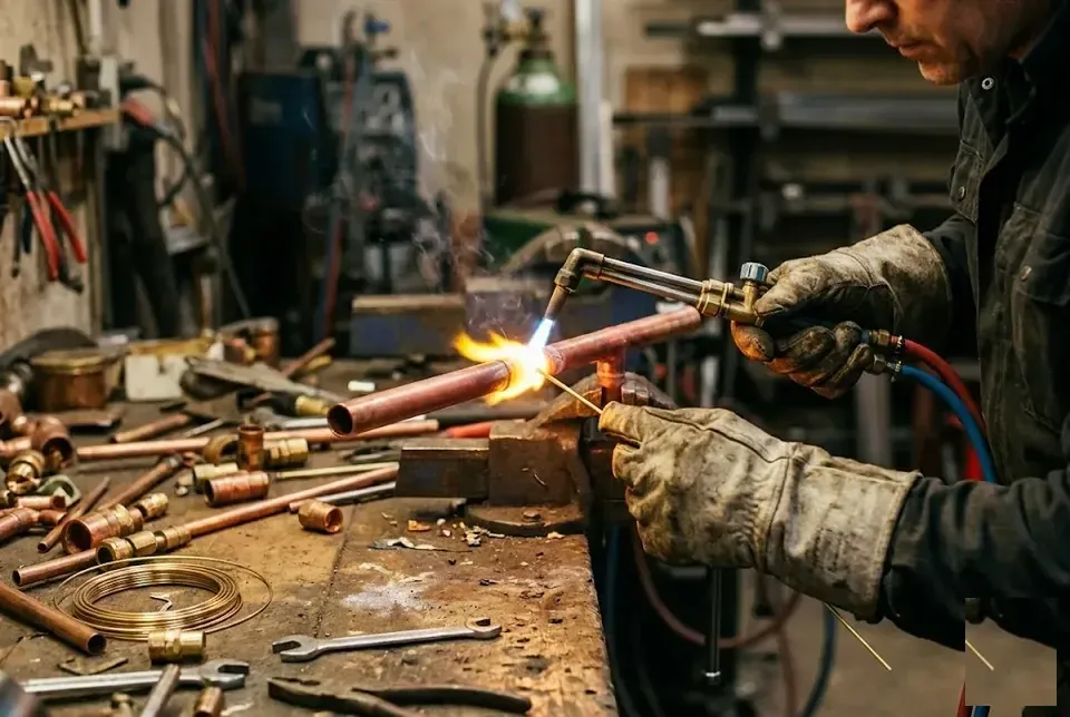
If TIG welding is unavailable, copper can be welded with a gas torch or an electrode. Let us look at the features of each method and when to use them.
Gas welding of copper — oxy-acetylene with flux
Gas welding is performed with an acetylene-oxygen flame using a flux — usually borax (sodium tetraborate), which dissolves the oxide film and protects the melt from oxidation. When heated, borax melts at 741°C, reacts with CuO to form low-melting borates — they float to the surface of the weld and are removed after cooling. In gas welding, an acetylene-oxygen torch with a №2–4 nozzle is used for a metal thickness of 1–5 mm, and the filler rod is copper of grade M1 or M2 without deoxidising agents, since the flux takes on the protection itself. The flame must be strictly normal (neutral) — an excess of oxygen causes strong oxidation, while an excess of acetylene carburises the weld, making it brittle; the flame is adjusted by a clear torch outline without soot.
Electrodes for welding copper — Komsomolets-100, OZB-2F and a carbon electrode
For manual metal arc (MMA) welding of copper, specialised electrodes are used — “Komsomolets-100” (a copper core with a fluoride coating) and OZB-2F (with a fluorite-calcium coating), and for preheating and welding thick copper — a carbon electrode. “Komsomolets-100” is the main choice: its core of cathode copper M00k (99,97% Cu) gives minimal contamination of the weld, and the coating contains fluorides and silicates that stabilise the arc on direct current. OZB-2F is inferior in arc stability, but is cheaper and suitable for repair work on thick-walled parts from 5 mm. The carbon (graphite) electrode is used not to form the weld, but for preheating massive parts or as a non-consumable electrode in alternating current welding — it is not a filler but a tool. “Komsomolets-100” gives a more stable arc and less spatter than OZB-2F, but requires strict baking before welding (2 hours at 200°C) — a damp coating causes pores in the weld because of hydrogen.
MMA copper welding modes — current and preparation
Welding copper with an ordinary inverter is possible on direct current with reverse polarity (plus on the electrode) at a current of 40–50 A per 1 mm of electrode diameter — for a 3 mm electrode this is 120–150 A. On thick workpieces (10–20 mm) the current is raised to 200–300 A, but here the arc length is critical: a short arc (1–2 mm) reduces spatter and lowers heating of the heat-affected zone. Before welding, the part is cleaned to a shine — the oxide film is removed mechanically or by etching in 20–30% sulphuric acid, and the edges are prepared with a V-shaped bevel at an angle of 60–70° at a thickness of 5 mm and above. Unlike TIG, in MMA welding of copper preheating is essential even for thin parts (a minimum of 200°C), otherwise the arc will be unstable and the weld will have lack of fusion and porosity.
Comparison of copper welding methods — when to use which
| Welding method | Copper thickness | Weld quality | Speed | Equipment |
|---|---|---|---|---|
| TIG (argon) | 0,5–20 mm | High, dense weld | Medium | TIG inverter, argon cylinder |
| Gas (acetylene) | 0,5–5 mm | Average, porosity possible | Low | Torch, acetylene and oxygen cylinders |
| MMA (electrode) | 3–20 mm | Average, a lot of slag | High | Standard inverter |
| MIG (semi-automatic) | 1–10 mm | High, productive | High | MIG machine, copper wire |
Copper welding technology step by step — from preparation to inspection
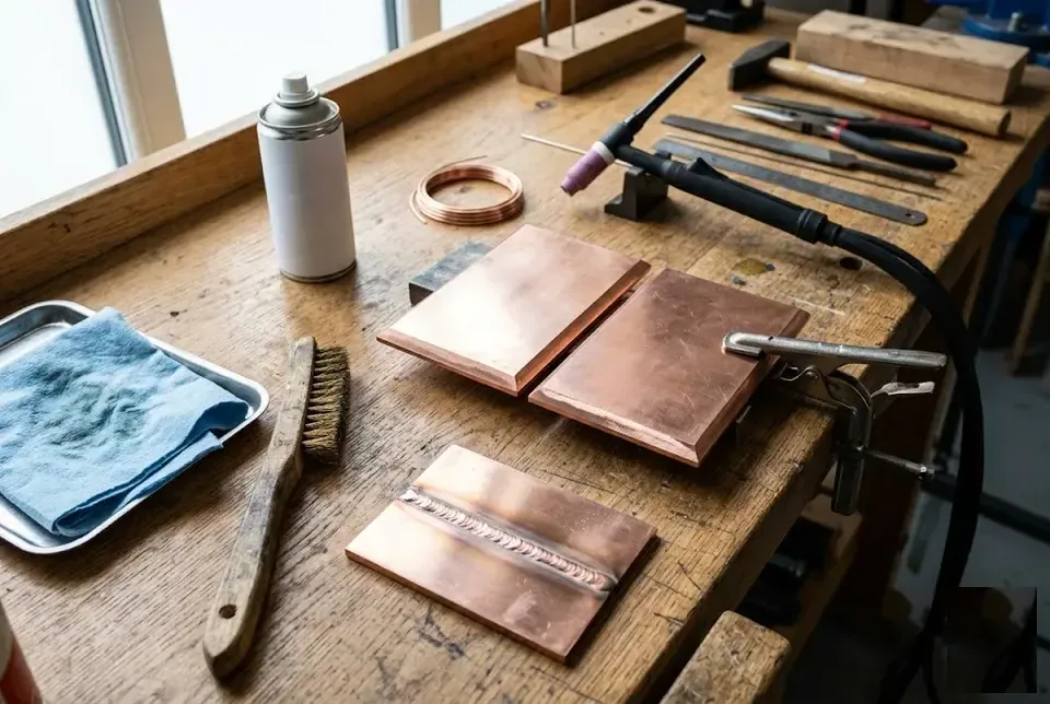
A step-by-step guide for a welder tackling copper for the first time. From cleaning to final inspection — all stages with specific parameters.
Surface preparation — cleaning and degreasing
Preparing copper for welding includes mechanical cleaning to a shine with a grinding wheel or a stainless steel brush followed by degreasing with acetone or white spirit — this removes the Cu₂O oxide film and moisture, the main sources of porosity in the weld. The oxide melts at 1235°C, which is above the melting point of copper itself (1083°C) — it does not go into the melt but remains as solid inclusions, and moisture on the edges decomposes into hydrogen and oxygen when heated, with the hydrogen diffusing into the pool and forming gas cavities during crystallisation. After cleaning, you must not touch the edges with bare hands — grease from your fingers has the same effect as a non-degreased surface. Copper should be cleaned immediately before work: after 2–3 hours a new oxide layer forms in the air, degrading weld quality, especially in gas welding.
Preheating — temperature and methods
Preheating copper is essential for all methods: at a thickness of up to 3 mm, 150–200°C is enough; at 3–6 mm — 250–350°C; above 6 mm — 400–500°C; and on thick busbars from 10 mm — up to 600°C. The reason is the material's high thermal conductivity (400 W/m·K versus 50 for steel). Without preheating, the heat instantly drains into the mass of the part — the arc or flame does not create a weld pool, the filler “sticks” without penetrating the edges, and the weld holds only by surface adhesion. To control the temperature we use temperature-indicating crayons or a pyrometer — heating “by eye” based on the temper colour does not work for copper, as it changes shade at 600–700°C, when it is already overheating and oxidation begins. Preheating is done with a gas torch, a carbon electrode or in a furnace; the main thing is to heat the whole part evenly, not just the area of the future weld, otherwise the coefficient of thermal expansion means that local heating creates deformation and hot cracks.
Choice of filler and welding technique
For a beginner welder on a copper tube joint it is better to choose TIG with a deoxidising rod — phosphor bronze CuSn6P or a copper-silicon alloy CuSi3Mn: these filler metals forgive settings mistakes and produce a dense weld even with little experience. Phosphorus binds oxygen in the melt into phosphates that float out into the slag, while silicon deoxidises the copper and increases the fluidity of the pool — for thick-walled parts (busbars, housings) we use pure copper М1 with a borax-based flux, but this option requires precise settings and preheating. The technique of running a weld on copper differs from steel: the arc is short (2–3 mm), the torch is held at an angle of 70–80°, the filler metal is fed using the forehand technique — this preheats the edges and prevents the molten pool from flowing out, and on vertical welds over 4 mm thick graphite or copper backing is mandatory, otherwise the melt flows out on the reverse side in beads.
Weld quality control — visual and instrumental
A quality copper weld should be dense, free of porosity and cracks, with a uniform fish-scale structure — visually it differs from a steel weld by its lighter, pinkish-golden tint. Typical defects: porosity in the form of small craters on the surface, hot cracks along the weld axis that become visible after cooling, and lack of penetration — the edges are not fused with the filler metal, a gap is visible between the part and the deposited metal, and the latter occurs precisely because of insufficient preheating or low current. On critical structures (pressure pipes, current-carrying busbars) we carry out hydrotesting or capillary inspection using dye penetrant testing after work — porosity and microcracks in copper are often invisible to the eye but show up under load, and a missed defect can cost the system its seal.
Specifics of welding copper alloys — brass, bronze, cupronickel
Each copper alloy requires its own approach — what works for brass will ruin cupronickel. Let us look at three materials and advise which filler metal to choose.
Brass welding — the zinc burn-off problem and protection
When working with brass, zinc (vaporisation temperature 907°C) evaporates, forming a poisonous white zinc oxide fume, while the weld becomes porous and loses strength — to minimise burn-off, weld at minimum current with a short arc and use a filler with a higher zinc content. Brasses with a zinc content of up to 20% (L80, L90) can be welded with argon without flux: they behave stably, there is almost no fume, and the weld is sound. But high-zinc brasses (L63, LS59-1) with 35–40% zinc cause intense boiling of the pool and thick fume — in such cases we use an LK 62-0,5 rod with silicon, which suppresses evaporation, otherwise the weld becomes covered with blowholes. Zinc oxide fumes cause “metal fume fever” (chills, a temperature 4–8 hours after work) — so extraction at the workplace and a P3 class filter respirator are essential, and ventilation must run throughout the process and for a further 15 minutes afterwards.
Bronze welding — tin, aluminium, silicon
Tin bronze (БрОЦ) is prone to hot cracks due to its wide crystallisation range, so it is welded with minimal preheating (100–150°C) and a filler metal close in composition to the base metal, while aluminium bronze (БрАЖ) requires special rods with aluminium and iron and preheating to 200–300°C. БрОЦ 4-3 — is a classic for TIG welding: a filler metal of the same composition produces a weld almost indistinguishable from the base metal in colour and mechanics, but the slightest overheating above 200°C — and cracks 2–5 mm long run along the grain boundaries. With БрАЖ 9-4 it is simpler: aluminium forms a refractory oxide film that hinders fusion, so before work we clean the edges with a stainless steel brush and work on alternating current — it breaks down the oxide. Silicon bronze (БрКМц) is considered the most weldable — it has a narrow crystallisation range and does not require complex settings, so it is often chosen for decorative items and art welding.
Cupronickel welding — features and modes
Cupronickel (МН19, МНЖМц) contains nickel, which provides high corrosion resistance, but during welding it requires minimal preheating (to 100–150°C) — because its thermal conductivity is close to that of steel, it does not need the strong heating that pure copper does. In home conditions cupronickel is welded with argon at 40–80 A (depending on thickness: a spoon 1,5 mm — 40 A, a kettle 2,5 mm — 70 A), the filler metal used is МНЖМц 30-1-1 — which produces a weld resistant to brine and acids. The main problem is deformation of thin-walled items (cookware), so welding is done in short sections (10–15 mm) with pauses for cooling and always with argon purging on the reverse side of the weld for protection against oxidation — without it the weld turns black and loses its corrosion resistance.
Table — selection of filler for different copper alloys
| Alloy | Recommended filler | Welding specifics |
|---|---|---|
| Brass (L63, LS59-1) | LK 62-0,5 rod (with silicon) | Suppresses zinc burn-off and reduces fume generation |
| Tin bronze (BrOTs) | BrOTs 4-3 rod | Similar composition, minimal susceptibility to hot cracking |
| Aluminium bronze (BrAZh) | BrAZh 9-4 rod | Requires preheating to 200–300°C, filler with aluminium and iron |
| Cupronickel (MN19) | MNZhMts 30-1-1 rod | Welding in short sections, argon purging from the reverse side |
If you weld brass with a tin rod, the zinc will burn out completely, the weld will become porous, and during hydrotesting at 6 atm it will leak along its entire length. Choose the filler metal precisely for the alloy — this saves time and nerves.
Copper welding defects and how to avoid them
Let us examine the three main defects — porosity, cracks and lack of fusion — and how to prevent them.
Hydrogen porosity — the main cause of defects
Porosity in a copper weld occurs because of hydrogen, which at high temperatures (above 1083°C) dissolves actively in the molten metal and is then released during solidification, forming gas bubbles — especially when the metal is thicker than 3 mm. The source of hydrogen is moisture on the surface of the part, oil contamination and even hygroscopic fluxes that were not calcined. In Almaty workshops with high humidity in autumn and spring, porosity appears in 70% of cases if the edges are not treated with acetone immediately before welding. A filler with deoxidising agents — phosphorus (CuSn6P or CuP rods) or silicon — binds the hydrogen into refractory oxides, preventing it from being released as a gas. To avoid porosity, it is essential to thoroughly degrease the edges with acetone or white spirit, use a filler with deoxidising agents (phosphorus, silicon) and preheat the zone to 300–500°C to remove moisture.
Hot cracks — causes and prevention
Hot cracks in copper welds appear because of copper's high coefficient of thermal expansion (CTE) — during cooling the weld contracts more than the base metal, which creates tensile stresses in the heat-affected zone. On brass parts, for example on radiator manifolds, cracks run along the grain boundaries, especially if the alloy contains more than 15% zinc — when heated, the zinc evaporates, the weld becomes porous and loses ductility. In PROFI-DOM practice, cracks on copper busbars 6–8 mm thick occurred when trying to weld them without preheating at a current of 200 A — the weld burst 10–15 seconds after the arc ended. Prevention of cracks includes preheating to 300–500°C (reduces the temperature gradient), the use of fillers with deoxidising agents and welding in short runs with peening of each layer.
Incomplete root penetration — how to ensure full penetration
Lack of root penetration is a consequence of high thermal conductivity: heat rapidly dissipates into the body of the part without managing to melt the root, especially on metal more than 4 mm thick without preheating. At Almaty repair depots where copper air conditioner tubes 16–22 mm in diameter are welded, lack of root penetration is a frequent cause of freon leaks if the welder has not increased the current from the usual 90 A to 120–130 A. Edge preparation at an angle of 60–70° with a root face of 1–1,5 mm allows the arc to reach the root, while preheating with a gas torch to 400°C reduces heat dissipation by 2–3 times. To guarantee root penetration, an increased welding current is used (20–30% higher than for steel of the same thickness), edge preparation at an angle of 60–70° and preheating to 300–500°C — this compensates for heat dissipation.
Table of defects, causes and methods of elimination
| Defect | Cause | Method of elimination |
|---|---|---|
| Porosity | Hydrogen from moisture and contaminants | Degreasing, preheating to 300–500°C, filler with deoxidizers |
| Hot cracks | High CTE, rapid cooling | Preheating, peening the weld, short passes |
| Incomplete root penetration | High thermal conductivity, low current | Increased current by 20–30%, edge bevelling, preheating |
| Weld oxidation | Insufficient gas shielding | Increased argon flow rate (8–12 l/min), back purging |
Conclusion
Welding copper and its alloys is a process where every stage affects the result: from cleaning the edges to choosing the filler and the cooling regime. We have put together five key principles that turn a difficult task into a reproducible technology.
Key takeaways
- The high thermal conductivity of copper is the main technological difficulty: without preheating to 300–500°C the weld does not penetrate, and the heat goes into the body of the part, increasing gas consumption and working time.
- Hydrogen embrittlement is the main cause of pores: thorough degreasing of the edges with acetone and the use of fillers with deoxidising agents (phosphorus, silicon) solve the problem in 90% without overheating.
- Each copper alloy requires its own filler metal and settings: brass — a silicon rod to suppress zinc burnout, bronze — a filler metal close in composition, cupronickel — minimal preheating to 200°C and argon purging without flux.
- Hot cracks are prevented by preheating and peening the weld, while lack of root penetration is prevented by increasing the current by 20–30% relative to steel of the same thickness and by correct V-shaped edge bevelling.
- Having mastered these principles, you can weld copper and its alloys to industrial quality standards — even in a workshop or garage, without expensive equipment.