
Welding aluminium and steel: technologies for joining dissimilar metals
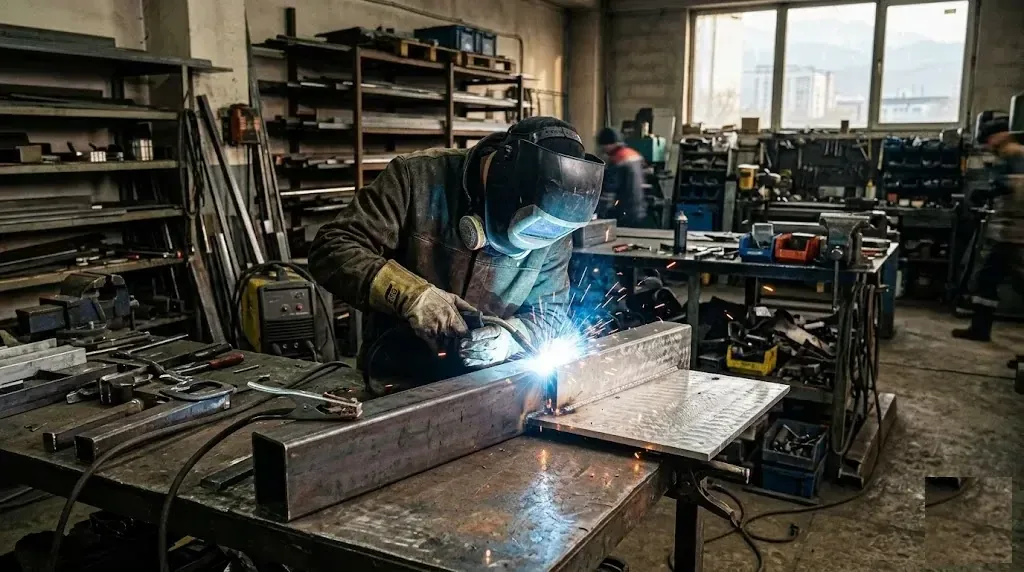
Welding aluminium and steel directly is impossible because of the formation of brittle intermetallics. In production, bimetallic transition inserts, welding through a zinc coating or solid-state methods are used. Aluminium itself is welded with TIG using argon or MIG with a semi-automatic welder, with mandatory surface preparation and the correct choice of filler.
Why aluminium and steel cannot be welded directly
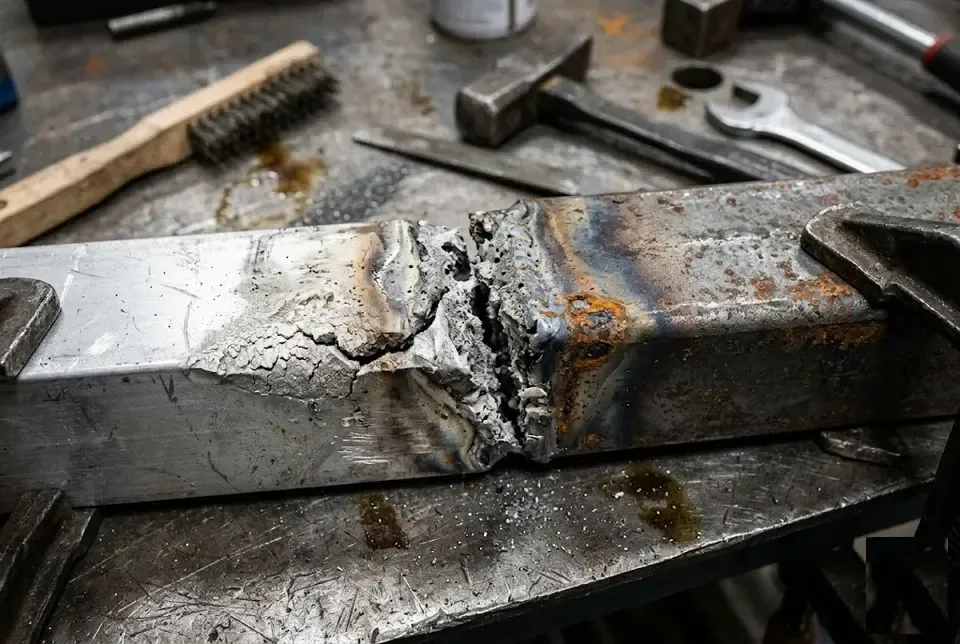
Welding aluminium and steel runs up against four physicochemical barriers — intermetallics, the difference in melting points, different thermal expansion and the oxide film, which turn a direct weld into a brittle and unreliable one.
FeAl₃ and Fe₂Al₅ intermetallics — the main cause of a brittle weld
In direct welding of aluminium to steel, iron and aluminium form brittle intermetallic phases FeAl₃ and Fe₂Al₅, which make the weld brittle. These compounds lack ductility — they crystallise in the fusion zone within milliseconds as soon as the temperature in the weld pool exceeds 650°C. The thickness of the intermetallic layer is critical: with a layer thicker than 10 µm, strength drops by a factor of 3–5, and the joint fails under bending or vibration. In PROFI-DOM practice this shows up when repairing aluminium structures with steel inserts — the weld looks intact visually, but cracks at the phase boundary already during installation. Even brief overheating triggers the growth of these phases within milliseconds — heat input must be controlled more strictly than on a homogeneous metal.
Difference in melting points — aluminium melts while steel stays solid
Aluminium melts at 660°C, steel at 1500°C, so during welding the aluminium turns to a liquid phase while the steel remains solid, which prevents fusion. Liquid aluminium does not wet the solid steel surface — instead of a common metal weld forming, mechanical sticking occurs, which in practice flies off at the first impact. When repairing aluminium radiators with steel unions, an attempt to weld the joint with a direct arc produces not an alloy but a porous crust a fraction of a millimetre thick. Even if a melted layer appears on the steel side, its strength does not exceed 50–80 MPa — that is 4–5 times lower than that of the base aluminium alloy. Liquid aluminium does not wet solid steel — instead of fusion, mechanical sticking forms, which fails under load.
Different thermal expansion — thermal stresses and cracks
The coefficient of thermal expansion of the metal is almost twice that of steel (23,1×10⁻⁶ 1/°C versus 12×10⁻⁶ 1/°C), so when the weld cools, thermal stresses of up to 200–300 MPa arise — this is the yield strength of the aluminium alloy. On long joints, transverse cracks appear even at a weld length of 200–300 mm, radiating from the centre to the edges. In local workshops this problem is solved by preheating the steel part to 150–200°C to reduce the shrinkage gradient during cooling. Even if a weld without intermetallics is obtained, the difference in CTE under cyclic loads (heating–cooling) gradually destroys the joint — a bimetallic transition joint is required on critical components.
Al₂O₃ oxide film — a refractory barrier on the metal surface
The Al₂O₃ oxide film melts at 2050°C — higher than the welding arc temperature — so it does not break down and blocks the fusion of aluminium with steel. A film 5–10 nm thick instantly re-forms on a cleaned surface on contact with air, and if you weld on direct current, the oxide remains an insurmountable barrier between the molten metal and the steel. In Almaty workshops this problem is solved with alternating current (AC TIG), which destroys the oxide by cathodic sputtering during the positive half-cycle — without this the seam comes out with oxide inclusions and a loss of tightness. The film re-forms within fractions of a second after mechanical cleaning, so the process is carried out on alternating current, which destroys the oxide by cathodic sputtering.
How aluminium and steel are joined in industry
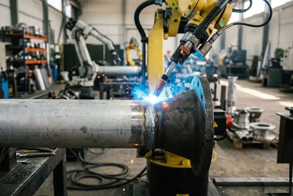
Let us examine all industrial methods of joining aluminium to steel — from bimetallic transition inserts to explosive and friction welding. Each method solves the intermetallic problem in its own way, and the choice depends on thickness, load and equipment availability.
Al-St bimetallic transition joint — the most reliable method
A bimetallic transition joint is a ready-made plate of steel and aluminium alloy layers joined by explosion welding, to which both parts can then be welded using conventional methods. Under factory conditions, a controlled intermetallic layer 1–3 µm thick forms at the interface — enough for a metallurgical bond, but too little for brittle fracture. Industry produces transition joints for any thickness: from 2 mm for sheet structures to 40 mm for pipeline flanges with working pressures up to 16 MPa. In the oil and gas sector of Almaty, such plates are installed at the connection points between aluminium heat exchangers and steel manifolds — this prevents corrosion failure after 2–3 seasons. The transition joint acts as a buffer — the intermetallics have already formed under factory conditions in a controlled thin layer, and they do not grow during subsequent welding.
Welding through zinc coating — an accessible method for thin parts
A zinc coating on steel serves as an intermediate layer that blocks the formation of FeAl₃ intermetallics — zinc binds the aluminium, preventing it from reacting with the iron. In practice this looks like this: the steel part is hot-dip galvanised (a layer of 20–50 µm), then the aluminium overlay is welded with a TIG torch at a minimum current of 30–50 A — the zinc melts at 420°C and fills the gap, preventing the aluminium from contacting the steel directly. In car body workshops across Almaty this method is used in repairing sills and arches, where 1–1,5 mm aluminium sheet is joined to the galvanised steel of the body. The method works only on thin-walled parts (up to 2 mm) and requires precise temperature control — zinc evaporates at 907°C, and overheating destroys the protective layer.
Explosion, friction and diffusion welding — solid-phase methods
Explosive welding, friction stir welding (FSW) and diffusion welding join aluminium to steel without melting the metals, which eliminates the formation of brittle intermetallics. In explosive welding, a steel plate is accelerated by detonation to 300–500 m/s and collides with the aluminium — in the contact zone high pressure (up to 10 GPa) is generated, which displaces the oxide film and creates a strong bond without a liquid phase. The FSW method for aluminium-steel assemblies is used in Almaty plants in the manufacture of vacuum chamber bodies — a rotating tool made of tool steel stirs the aluminium with a thin layer of iron, forming a composite weld without cracks. These methods are used on large industrial assemblies — bimetallic sheets, pipe transitions, ship hulls — where high joint strength is required.
Braze welding with silver filler metal — for small parts
Brazing-welding with silver solder joins aluminium to steel through molten solder, which serves as a buffer layer and does not form intermetallics. PSr-72 (72% solder (silver, 28% copper) melts at 779°C — below the temperature at which FeAl₃ forms — so the aluminium and iron remain separated by a ductile interlayer. In the repair of aluminium radiators on the Almaty market, this method is used to solder cracks in the tubes: a fluoride-based flux removes the oxide film, the solder flows into the 0,1–0,3 mm gap, and the joint holds pressure up to 2 atm. The method is suitable for repairs and small parts (radiators, tubes), but the joint strength is lower than that of a bimetallic adapter — up to 60% of the strength of the base metal.
Comparison of methods for joining aluminium to steel
| Joining method | Principle | Thickness of parts | Weld strength | Where it is used |
|---|---|---|---|---|
| Bimetallic transition joint | Ready-made Al-St plate | Any | 90–100% | Pipelines, flanges, load-bearing structures |
| Welding through zinc coating | Zinc as a buffer | Up to 2 mm | 70–80% | Thin-walled parts, body repair |
| Explosion welding | Shock wave, without melting | 5–50 mm | 95–100% | Large sheets, shipbuilding |
| Friction stir welding (FSW) | Solid phase, stirring | 3–20 mm | 85–95% | Aviation, railcar manufacturing |
| Diffusion welding | Heating + pressure | Any | 90–100% | Vacuum assemblies, electronics |
| Braze welding with filler metal | Molten filler metal | Up to 3 mm | 50–60% | Radiator repair, small parts |
On critical structures (pipelines, load-bearing elements), the bimetallic transition joint remains the only industrially reliable solution.
TIG welding of aluminium — technology, modes, filler metals
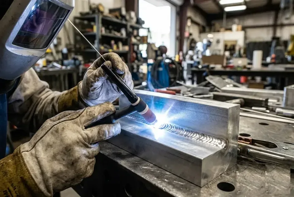
TIG welding with argon is the main method for aluminium. Let us look at what current is needed, how to set the AC balance, which fillers to choose and how to avoid burning through thin sheet.
Why TIG on aluminium uses alternating current (AC) only
In this process, alternating current (AC) is used, which in the positive half-cycle destroys the oxide film by cathodic sputtering, and in the negative half-cycle provides penetration. Direct current (DC) on straight polarity (electrode negative) cannot cope with the oxide — the arc dances over the surface, the weld comes out dirty, with Al₂O₃ inclusions. On reverse polarity (electrode positive), the oxide is destroyed excellently, but the electrode overheats within 10–15 seconds — the tungsten melts and contaminates the pool. Alternating current solves both tasks: in one half-cycle (EP) it knocks off the oxide, in the other (EN) it heats the part. On thin sheet of 1–2 mm, one should tune the AC frequency to 80–120 Hz — a higher one gives a narrow concentrated weld and reduces the heat-affected zone. Before work, thoroughly clean the aluminium with a stainless steel brush — even a thin layer of oxide noticeably hinders arc striking on AC.
Setting the AC balance — the ratio of cleaning to penetration
The AC balance on a TIG machine controls the ratio between oxide cleaning (EP — electrode positive) and penetration (EN — electrode negative), usually 70/30 or 65/35. The standard setting for most aluminium alloys is 70% for penetration and 30% for cleaning: the arc is stable, the bead is clean and penetration is sufficient. If the part has a thick oxide film (cast aluminium after sandblasting or long storage), it is worth increasing EP to 35–40% — — the arc knocks off the oxide more aggressively, but the bead becomes wider and duller. On clean rolled stock, on the contrary, EP can be reduced to 20–25% — — this gives a deep, narrow bead with a shiny surface. On Kemppi, Fronius or Lincoln Electric machines the balance is set in percentages or conventional units — always check on a test piece before the actual part. Too much cleaning (more than 40% EP) gives a dull, wide bead but reduces penetration depth — on thin sheets this leads to burn-through.
Tungsten electrode and filler rods — ER4043 or ER5356
In TIG welding of aluminium, a lanthanated tungsten electrode WL20 (grey tip) is used, with ER4043 (AlSi5) filler for cast alloys and ER5356 (AlMg5) for wrought alloys. Lanthanated tungsten (1,8–2,2% La₂O₃) carries current better than thoriated, produces no radioactive dust when sharpening and works stably on AC without splitting the tip. The electrode diameter is chosen according to current: 1,6 mm — up to 100 A, 2,4 mm — up to 180 A, 3,2 mm — up to 250 A. ER4043 (5% filler (silicon) flows well, gives a beautiful shiny weld and fewer cracks on silumins and castings — optimal on frames, housings and cast components. ER5356 (5% (magnesium) is stronger in tension and more resistant to corrosion in marine/outdoor environments — it is used on boats, handrails and outdoor structures. ER5356 gives a stronger weld outdoors, but when working with cast alloys (silumin) it forms cracks — here only ER4043 will do.
Which gas is needed in TIG welding of aluminium
In TIG welding of aluminium, pure argon (100%) is used — it provides a stable arc and good cleaning of the oxide film. The flow rate is set at 7–12 l/min depending on the current: for 100 A — 7–8 l/min, for 250 A — 10–12 l/min. Argon is heavier than air and protects the pool well in the horizontal position, but outdoors or in a draught the flow rate is increased by 20–30%. The addition of helium (argon+helium, usually 25–50% He) increases heat input on thick parts (from 8 mm) — the arc becomes hotter and heats massive aluminium faster, but requires 15–20% more current and costs more. Pure argon is cheaper and covers 90% of aluminium tasks — helium is used rarely, only on thick plates of 10+ mm. The addition of helium increases heat input on thick parts (from 8 mm), but requires a higher gas flow rate and greater current.
TIG welding modes for aluminium by thickness — current, speed, filler diameter
| Thickness, mm | Current (AC), A | Tungsten diameter, mm | Filler diameter, mm | Welding speed, mm/min |
|---|---|---|---|---|
| 1–2 mm | 60–100 | 1,6 | 1,6–2,0 | 200–300 |
| 3–4 mm | 120–180 | 2,4 | 2,4–3,2 | 150–250 |
| 5–6 mm | 180–250 | 3,2 | 3,2–4,0 | 100–200 |
| 8–10 mm | 250–350 | 4,0 | 4,0–5,0 | 80–150 |
Thin aluminium (1–2 mm) requires pulsed mode — alternating current pulses and pauses gives time to cool and prevents burn-through. The pulse is set up as follows: peak current 80–100 A, background current 30–40 A, frequency 2–4 Hz. On 1 mm sheet with standard AC without a pulse it is hard not to burn through — even experienced welders keep a speed of 250–300 mm/min and minimum current. On thick workpieces (from 6 mm), preheating with a torch to 150–200 °C speeds up the process and reduces the risk of cold cracks at the start of the weld.
Semi-automatic (MIG) welding of aluminium — wire, gas, settings
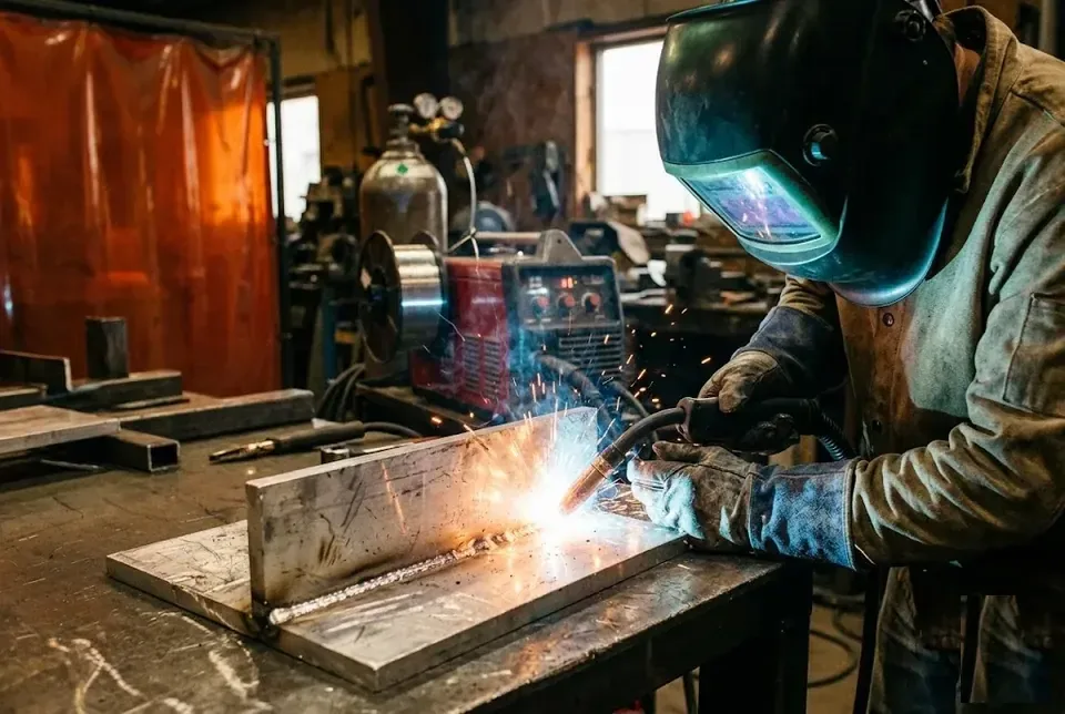
MIG welding of aluminium differs from welding steel — you need a special torch, a pulsed mode and the right wire. Let us go through all the nuances.
Can aluminium be welded with an ordinary semi-automatic welder designed for steel
A standard semi-automatic welder for steel is not suitable for aluminium — soft aluminium wire crumples in a steel liner, and a standard torch does not provide a stable feed. In a standard wire feed path, wire with a diameter of 0.8–1.2 mm is squeezed by the rollers and jams in the metal spiral of the liner, especially over a hose length of 3 metres or more. That is why aluminium always uses a PTFE liner with a low coefficient of friction and a push-pull torch, where the pushing mechanism in the machine body is duplicated by a pulling roller in the torch handle. This design pushes the soft wire the full length of the lead up to 8 metres without loops or jerking. Even if the wire is changed, without a push-pull torch and a PTFE liner the feed will be jerky, leading to an uneven seam and frequent arc breaks.
Which wire is needed for MIG welding of aluminium
In MIG welding of aluminium, ER4043 (AlSi5) or ER5356 (AlMg5) wire with a diameter of 0.8–1.6 mm is used — the choice depends on the alloy and the thickness of the parts. ER4043 wire with a silicon content of 4.5–6% gives a more fluid pool and fills gaps better, so it is preferred on cast alloys (silumin) and thin-walled structures up to 4 mm. ER5356 with magnesium 4.5–5.5% provides a weld with a tensile strength of up to 280 MPa versus 240 MPa for ER4043 —; it is used for frames, boat hulls and structures made of wrought alloys 5083, 6061. The wire diameter is chosen according to thickness: 0.8–1.0 mm for 1–3 mm, 1.2 mm for 4–6 mm, 1.6 mm for 8–12 mm. ER5356 wire produces a stronger and more corrosion-resistant weld, but when welding cast alloys (silumin) it is prone to cracking — here ER4043 is better.
Pulse mode (pulse MIG) — why it is needed on aluminium
The pulsed MIG mode (pulse) alternates a current pulse to detach a droplet with a pause for cooling — this reduces heat input and allows welding thin aluminium without burn-through. In the normal mode (short arc), on aluminium droplets are transferred in large portions at a frequency of 30–60 Hz, which gives a coarse scale and spatter losses of up to 10–15% of the filler metal. Pulse MIG operates at a frequency of 60–300 Hz: the peak current pulse (200–400 A) detaches a droplet strictly once per cycle, while the pause current (40–80 A) maintains the arc without melting. As a result, the weld has a fine scale, and heat input is reduced by 20–30% — — this is critical on aluminium 1.5–3 mm thick, which simply burns through without pulsing. Without pulsing, it is difficult to control metal transfer on aluminium — droplets become large, the arc unstable, and the weld coarse and spattered.
Which gas to use in MIG welding of aluminium — pure argon or a helium mix
In MIG welding of aluminium, pure argon (100%) is used on parts up to 6 mm, while on thick parts (from 8 mm) a mixture of argon with helium (25–50% helium) is used to increase heat input. Pure argon gives a stable arc and good cleaning of the oxide film at currents up to 250 A, but its thermal conductivity is low: on thick aluminium of 10–12 mm the arc wanders and penetration is insufficient. A helium mixture (Ar + 30% He) raises the arc temperature by 200–300 °C, which increases penetration depth by 30–50% and allows welding at speeds up to 80 cm/min. Gas consumption increases accordingly: for argon 14–18 l/min, for the helium mixture — 20–25 l/min due to the lower density of helium. Helium is 3–5 times more expensive than argon, so in series welding of thick aluminium preheating of the part is often used instead of a mixture — it is cheaper.
MIG welding modes for aluminium by thickness — current, wire feed speed, gas
| Thickness, mm | Current (pulsed), A | Wire feed speed, m/min | Wire diameter, mm | Argon flow rate, l/min |
|---|---|---|---|---|
| 3–4 mm | 120–160 | 5–7 | 1.0 | 14–16 |
| 5–6 mm | 160–220 | 7–9 | 1.2 | 16–18 |
| 8–10 mm | 220–280 | 9–11 | 1.6 | 18–20 |
| 10–12 mm | 280–350 | 11–14 | 1.6 | 20–24 |
The wire feed speed for aluminium is higher than for steel (by a factor of 1.5–2) because of its lower density and rapid melting. If on steel at a current of 200 A the wire feed of 1.2 mm is 4–5 m/min, then on aluminium at the same current it is 7–9 m/min. When setting up, set the pause current to 40–60 A so as not to overheat the thin edge — this reduces the risk of burn-through on 3–4 mm parts.
Aluminium welding technology — preparation, thickness-based parameters, inspection
The quality of the joint on 50% depends on preparation. Let us examine the mandatory steps — from degreasing to cooling control.
Degreasing with acetone — the first and mandatory step
Before work, the part must be degreased with acetone or alcohol — oils and greases decompose on heating into hydrogen, which causes pores in the seam. Markings, stickers and residual preservative grease are removed with a lint-free cloth moistened with acetone — wipe twice, turning the cloth. The weld zone and the area 20–30 mm from the edge are treated especially thoroughly: that is where contaminants enter the weld pool. Technical ethyl alcohol gives a similar result, but acetone evaporates faster and leaves no streaks. Do not use petrol or solvents with an oily residue — they leave a film that causes the same pores as the original contamination.
Removal of the oxide film — with a stainless steel brush or by etching
The Al₂O₃ oxide film is removed mechanically — with a stainless steel brush (used only on aluminium, not on other metals) — or by chemical etching in an NaOH solution. The mechanical method is simpler: a brush with stainless steel bristles 0,2–0,3 mm in diameter is passed along the edges until a matte shine appears without dark spots. Chemical etching is used on complex profiles — immersion in a 10–15% solution of caustic soda for 1–3 minutes, followed by rinsing with water and neutralisation in dilute nitric acid. The oxide must be removed immediately before work: in air the film re-forms within 20–30 minutes, and if there is a delay the procedure is repeated. A brush made of ordinary steel leaves iron particles on the aluminium, which form intermetallics and corrosion sites during welding — use only stainless steel.
Edge preparation — V-groove and X-groove for thick aluminium
On aluminium from 4 mm thick, edge preparation is required — V-shaped (up to 15 mm) or X-shaped (over 15 mm) with an opening angle of 60–70°. A root face of 1–2 mm is left — this prevents burn-through of the weld root at arc start. Cleaning after preparation is done with a file or scraper, removing burrs and dross: they become sources of oxide inclusions. On parts up to 4 mm thick, preparation is not needed — it is enough to clean the edges with a brush and leave a gap of 1–1,5 mm for root penetration. Due to the high thermal conductivity of aluminium, preparation is done with a larger angle than for steel — otherwise heating will be insufficient and lack of fusion will appear.
Preheating the workpiece before welding — when and why
Aluminium more than 6 mm thick is preheated to 100–150°C before work — this reduces thermal shock, lowers the risk of hot cracks and improves root penetration. Preheating is done with a gas torch or an induction heater, with the temperature monitored by a contact thermometer or temperature-indicating crayon: the heated zone is a strip 100–150 mm wide on either side of the joint. Thin-walled parts (up to 3 mm) do not need preheating — they are heated by the arc itself, and extra heat only enlarges the heat-affected zone. On castings and thick forgings (from 10 mm) preheating is mandatory — without it the first pass leaves a root lack of penetration up to 2–3 mm deep. Overheating the metal above 200°C is dangerous — it loses strength in the heat-affected zone, and the weld becomes brittle even with no visible defects.
Aluminium welding technology — a step-by-step checklist
- Degrease the part with acetone or alcohol — remove oils, greases and markings from the weld zone and 20–30 mm from the edge.
- Remove the oxide with a stainless steel brush (for aluminium only, with 0,2–0,3 mm bristles) or by etching in 10–15% NaOH for 1–3 minutes.
- Prepare the edges in a V shape at a thickness of 4–15 mm (angle 60–70°, root face 1–2 mm) or in an X shape from 15 mm.
- Preheat the part to 100–150°C for thicknesses from 6 mm — with a gas torch or an inductor, monitoring with a thermometer.
- Weld with minimal delay after preparation: the oxide film recovers within 20–30 minutes in air.
- Cool slowly, without forced cooling with water or compressed air — rapid cooling causes thermal cracks in the seam and the heat-affected zone.
Welding defects in aluminium and how to avoid them
Even with ideal settings, working with aluminium produces defects if the behaviour of the metal is not taken into account — let us examine four typical problems and ways to prevent them.
Pores in the weld — causes and remedies
Pores in the weld occur because of hydrogen that enters the molten pool from moisture, dirt or an oxide film — as the metal solidifies, the hydrogen does not have time to escape and forms gas bubbles. In Almaty workshops with humidity swings in spring and autumn, condensation on a cold workpiece is the main culprit of porosity: as little as 0.1 g of water per 1 kg of metal is enough for the weld to become spongy. Degreasing with acetone or isopropanol is essential, but people often forget to dry the part — residual solvent also produces hydrogen. A gas line that draws in air through a loose connection adds oxygen, which oxidises the filler and creates chains of pores. Even microscopic moisture on the metal surface (condensation, coolant residues) causes porosity — that is why, before welding, the part must be degreased and dried, and the gas line checked for leaks.
Hot cracks — why they appear and how to prevent them
Hot cracks in aluminium welds occur during crystallisation, when shrinkage stresses exceed the strength of the semi-liquid metal — especially in alloys 5xxx and 6xxx with a wide crystallisation range. In practice, this looks like a rupture along the centre of the weld or along the fusion line, noticeable just a second after the pool solidifies. Alloy 6061 (AD33) cracks at the slightest excess of current if no filler is used — pure unalloyed aluminium cracks almost always. In the practice of PROFI-DOM craftsmen, who weld frames and attachments, hot cracks most often appear on thick metal (8-12 mm) when trying to weld with a single pair of passes. To avoid hot cracks, silicon (ER4043) or magnesium (ER5356) fillers are used, which narrow the crystallisation range, and both the welding current and the cooling rate are reduced.
Oxide inclusions and lack of fusion — visual diagnostics
Oxide inclusions look like dark spots or streaks inside the seam, while lack of fusion looks like non-fusion of the edges or the root of the seam, often with a gap visible on a fracture or during dye penetrant testing. When welding aluminium with argon, the oxide film is destroyed by alternating current, but if the cleaning before welding was only superficial, the remaining oxide floats into the seam and produces dense black inclusions. Lack of fusion at the root is a typical problem with semi-automatic MIG welding on thick sheet (from 6 mm), when the wire does not penetrate the lower edge due to low current or a small gap. Visual inspection is simple: a matte “fur coat” on the surface of the seam is a sure sign of oxide, and a concave root with a gap is lack of fusion. If there is a matte “fur coat” or black deposit on the surface of the seam, it is oxide that was not removed before welding; such a seam loses up to 50% of its strength and requires rewelding.
TIG vs MIG — which method produces fewer defects
| Parameter | TIG (argon-arc) | MIG (semi-automatic) |
|---|---|---|
| Porosity | Minimal (precise gas control) | Higher (depends on wire and gas feed) |
| Oxide inclusions | Rarely (AC arc cleaning) | Possible (with poor preparation) |
| Hot cracks | Less (lower speed, better control) | More often (high speed, more stress) |
| Lack of fusion | Rarely (penetration is easy to control) | Possible (especially on thick metal) |
| Speed | Low (10-20 cm/min) | High (30-80 cm/min) |
| Thickness | 0.5-6 mm (optimal) | 3-20 mm (optimal) |
For thin aluminium (up to 3 mm) and critical welds, TIG is chosen; for thick (from 4 mm) and series production — MIG with pulsed mode.
Conclusion
We have examined the key techniques for welding aluminium and joining it to steel. Here are five main points every welder should remember.
Key takeaways
- Welding aluminium and steel directly is impossible — brittle intermetallics form. Use bimetallic transition inserts, welding through a coating or mechanical joints.
- The oxide film is the main enemy of an aluminium seam. Remove it mechanically (with a stainless steel brush) or by etching, then weld without pause — the film re-forms within seconds.
- The choice of method depends on thickness and requirements: TIG (argon) — for thin aluminium and critical welds, MIG (semi-automatic) — for thick metal and series production.
- Edge preparation and preheating are mandatory for thick aluminium (from 6 mm). V- or X-shaped preparation, preheating to 100-150°C, temperature control with a thermometer.
- Defects — porosity, cracks, lack of fusion — are prevented by a clean surface, the correct filler, settings and shielding gas. Visual inspection and penetrant testing help identify them before operation.